Return Loss in Fiber Optic Couplers
When light is sent into an input Port of a fiber optic coupler, back-reflections can occur at the fiber-air interfaces of opposing output Ports. If the angle of these back-reflections is within the fiber's cone of acceptance, they will be guided and transmitted back to the illumination Port and/or the detection Port. This contributes to noise levels and can affect the quality of a measured signal, especially in low-light applications.
Typically, this effect is mitigated by using FC/APC connectors, which are polished at an angle of 8°, preventing back-reflections from being guided in standard single-mode optical fibers. When using optical fibers with higher numerical apertures, such as those used in Castor's DCF and multimode fibers, this 8° polishing is, however, not sufficient.
Available Connector Options
To optimize the return loss performances of our Wideband Multimode Circulators (WMCs) and Double-Clad Fiber Couplers (DCFCs), our team has developed dedicated fiber termination and connectors. High-angle connectors compatible with 0.22 NA and 0.39 NA fibers are now available for all our products, ensuring reduced back-reflections for a large bandwidth. For single-mode or narrowband modalities, we also offer AR-coated connectors. They are designed to effectively reduce the amount of back-reflections for a specific wavelength range. When using a fiber optic coupler for sensing applications, the 4th Port, opposite to the illumination Port, is typically unused, but can contribute to return loss, returning any residual power to the detection Port. Our team has developed an improved 2x1 packaging for DCFCs, including a high return loss termination at the 4th Port, improving overall SNR.


Specifications
The performance of high-angle connectors and AR-coated connectors was assessed and benchmarked against standard flat (0° polished) or APC (8° polished) connectors. The first table below shows return loss performances for 0.22 and 0.39 NA fibers. The values for the 0.22 NA fiber were measured on a WMC2. The values for the 0.39 NA were measured on a WMC3. A broadband white light source was used for all measurements. For DCFC units, measurements were performed at 633 nm for the DC530SE and at 850 nm for the DC780SE.

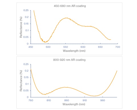
Anti-Reflective (AR) Coating Specifications
The graphs show spectral reflectance data for each available coating.
Optimized for DC530SE
- Wavelength range: 450-680 nm
- Return Loss <45 dB
Optimized for DC780SE2
- Wavelength range: 800-920 nm
- Return Loss <50 dB
The 2x1 packaging of some DCFC models is available on Thorlabs.com. For inquiries about specialized connectors, contact our team at sales@castoroptics.com.
Written by Audrey Laurence, Applications Scientist


